Data Sheet 50: Bootstrapping to Save Power – Part 2, Tension Stressing Continued
The first article in this series on bootstrapping appeared in Design Data Sheet 36. The reader should review that issue for an explanation of the purpose of bootstrapping and the basic operating principle.
Diagrams in this issue and in Design Data Sheet 36 illustrate tension stressing as in a steel cable being spooled between two drums. Essentially the same circuits and the same components can be used for compression stressing of a rigid material moving between two rollers. The only change would be to re-connect the two hydraulic motors to rotate in the correct direction to produce compression instead of tension stress. In a later issue we will discuss torsion stressing with bootstrapping circuits.
Complete Circuit
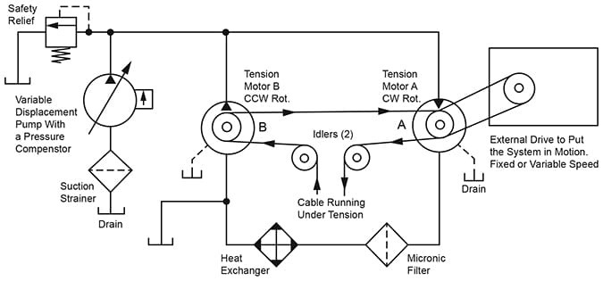
Figure 1. The left side of this diagram shows hydraulic components for tensioning the cable. The two motors, A and B, have identical displacement, they are exposed to the same fluid pressure, and are connected to drums of the same diameter, so there is no cable movement produced in this part of the circuit. Cable movement, at any speed desired, is produced by a completely separate external drive which may be electrical, hydraulic, or mechanical.
This is a form of closed loop circuitry. When the system is put into motion, oil discharged from Motor A, after passing through the filter and heat exchanger, is available to enter the inlet of Motor B.
For best performance and smoothest operation at low speeds, piston motors should be used. A small amount of oil is lost from the loop by internal slippage, and passes out the external drains. The only flow required from the variable pump is enough to make up slippage in the two motors.

Figure 1. Complete circuit for cable tensioning with a bootstrap circuit. Tension is maintained with the fluid
power system. A separate external drive keeps the cable traveling at the desired rate of speed.
Description of Components, Figure 1
Pump. The pump should be a variable displacement piston type unit with a pressure compensator control. It is required to work on one side of center, only.
Pump volume must be sufficient to make up internal slippage flow of itself and the two motors. Remember, that as the pump and motors wear, their slippage flow will increase, so the pump must be oversized to take care of increased slippage at some future time. If the pump volume should become insufficient to supply all slippage losses, the motors could not develop full tension on the moving cable.
Cable tension depends on the setting of the pump compensator, and the compensator should be adjusted for the tension required.
Relief Valve. This valve is expected only to absorb momentary pressure peaks developed by mechanical shocks on the system, During the short interval required by the pump compensator to swing the pump cam plate to a reduced angle. It should always be set at least 10% or 500 PSI higher than the pump compensator to prevent accidental continuous discharge across it which would overheat the system.
Hydraulic Motors A and B. Fixed displacement, piston-type motors, of hi-rotational construction, are recommended, although in some applications gear or vane-type motors may prove satisfactory. Motor B must be capable of reversible action. It must work as a pump if its shaft is forced backward against the direction it would run as a motor.
Both motors, of course, must have identical displacement, and should be connected to cable drums of the same diameter. However, their displacements may be unequal if cable drum diameters are selected to produce equal torques in opposite directions. Torques must be in balance.
If drum RPM must be low, say less than 500 RPM, the motors must be of a type which will operate smoothly at the selected speed. Slow speed motors with built-in speed reduction, such as Char-Lynn, may not work well when the shaft is driven backward to work like a pump.
Note: Each motor, by itself, must be sized to produce the entire torque needed for cable stress. Torques of both motors may not be added for total torque when they are pulling against each other.
Heat Exchanger. Most bootstrap systems, except those operating at high power, will not need a heat exchanger. Except for mechanical bearing friction, the only significant power waste entering the hydraulic oil as heat, is caused by slippage inside the pump and two motors.
If a heat exchanger should be needed, the return side of Motor A is the best location for its installation. Pressure is low and oil flow is high. The usual procedure is to select a model which, with the widest baffle spacing on the oil (shell) side will handle its flow at a velocity between 2 and 4 feet per second. Then, specify the number of passes on the water side (1, 2, or 4) according to volume of cooling water available. See main index for other information on heat exchangers and oil cooling.
Filter. In addition to the pump suction strainer, a good quality micronic filter should be included, and the ideal installation point is in the return line from Motor A either ahead of or following the heat exchanger. A relatively inexpensive model may be used since the pressure is quite low.
External Drive. This can be any kind of fixed or variable speed drive. If hydraulic, it should be entirely separate, and in no way connected with the hydraulic tensioning system, except that a common reservoir is permissible if the two sections are on the same elevation. A common pump should never be used for both tensioning and external drive because of possible interaction between the two systems.
Analysis of Oil Flow in the Tensioning Circuit
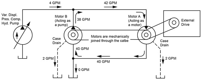
Figure 2. This is a stripped down flow diagram for the complete circuit of Figure 1, and illustrates the oil flow to be expected in various parts of the circuit, assuming the torques of the motors are balanced so as to produce no movement of the cable. Flows shown are those which appear after a typical system has been set in motion by the external drive to a speed where circulating oil in the loop exceeds the slippage flow of the motors.

Figure 2. This is a stripped down version of Figure 1, to illustrate flow in various parts of the circuit.
Example: Assume Motors A and B are piston-type units being driven at a speed which will deliver 40 GPM from the outlet of Motor A. Assume also that slippage flow of each motor is 2 GPM. Find the minimum oil flow required from the pump under these conditions.
Both motors are forced to rotate at the – same speed because of being tied together by the moving cable. Motor A requires an additional 2 GPM for internal slippage or a total of 42 GPM on its inlet. Motor A delivers 40 GPM to the inlet of Motor B, and 2 GPM is lost in internal slippage. Motor B delivers only 38 GPM back into the pump line, and the difference: 42 – 38 = 4 GPM must be supplied by the pump.
The bottom of the closed loop is vented to the reservoir. Any slight difference in motor characteristics would cause a small flow in this line either to or from the reservoir.
© 1990 by Womack Machine Supply Co. This company assumes no liability for errors in data nor in safe and/or satisfactory operation of equipment designed from this information.