Data Sheet 19: Clamp and Work Applications with Sequence Valves
The theme of this issue is clamp and work applications using sequence valves.
Clamp and work circuits use at least two cylinders, air or hydraulic. One cylinder advances first and clamps the workpiece in a fixture. Then the other cylinder(s) moves in with tools for cutting, drilling, pressing, forming, or other operations on the workpiece.
Sequence valves provide the most positive means for delaying advance of the work cylinder until the clamp has reached nearly full clamping force. The circuit should be arranged so both cylinders are controlled from a single 4-way valve by the operator. Starting of the work cylinder should be initiated by the rise of clamping pressure and not require extra attention by the operator.
Sequence Valves
A sequence valve is different from a relief valve in that the spring chamber is vented directly to atmosphere instead of to the outlet port on the valve. This allows full pressure to appear on both cylinders when they stall, instead of the pressure having to divide between them.
Air sequence valves are rare, as most manufacturers have discontinued their manufacture. But many sizes and kinds are readily available for hydraulics. An air relief valve can sometimes be substituted for an air sequence valve, but hydraulic relief valves should never be substituted for hydraulic sequence valves.

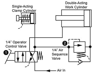
Figure 1. Simple Sequencing of Small Cylinders
Figure 1. This illustrates the basic principle of sequencing. It is a good working circuit if an air sequence valve can be purchased.
Sequencing is in the forward direction of both cylinders – they retract randomly. When the operator shifts and holds the manual or foot valve, 1, the single-acting clamp cylinder immediately extends and stalls at its forward position. This allows air pressure to build up to the opening pressure set on the sequence valve, and air can flow to the work cylinder. The work cylinder then advances to perform its work. When the operator releases Valve 1, both cylinders retract.

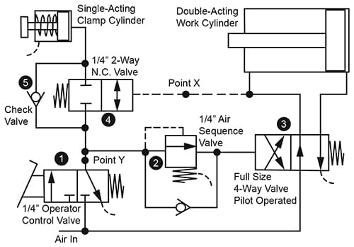
Figure 2. Sequencing a Very Large Work Cylinder, Both Directions
Figure 2. This circuit overcomes certain limitations of the preceding figure. Valve 2 can be an air sequence or relief valve or can be a low range hydraulic relief valve (if the air line is lubricated). It should be adjusted to open at about 50 PSI (on a 100 PSI supply line). When Valve 1 is shifted and held by the operator, the clamp cylinder will immediately extend and stall as in Figure 1. Pressure then builds up to about 50 PSI and opens the relief (or sequence) Valve 1. It must then build up by another 40 PSI (or so) to fully shift the 4-way Valve 3. Thus, at 90 PSI against the clamp, Valve 3 will fully shift. The full 100 PSI line pressure is working on both the clamp and work cylinders.
Important! To substitute a relief valve for the sequence valve, the relief valve must be operating into the pilot chamber of the next directional valve. Flow passing across the relief valve cannot be applied directly to the work cylinder because it will not be up to full line pressure. In this example, it could not be more than 50 PSI, the other 50 PSI being consumed by the relief valve.
In Figure 2 the sequencing takes place in both directions. Circuit action is as follows:
Operator shifts and holds Valve 1. Air flows to the clamp through check Valve 5 and 2-way Valve 4 (which is piloted open at this time). When the clamp bottoms out, the sequence valve opens and shifts Valve 3. The work cylinder advances. To retract the cylinders, the operator releases Valve 1 , and this vents the pilot of Valve 3, shifting Valve 3 to original position and retracting the work cylinder. Valve 4 remains closed until the rise in pressure in front of the work cylinder piston shifts it and vents the clamp.
Speed controls added to the work cylinder may be meter-out for its forward stroke but should be meter in for its return stroke to avoid prematurely releasing the clamp. If needed, a meter-in speed control can be added for the clamp at Point Y, and because of the small volume of air needed in the pilot of Valve 3, it should not noticeably affect the start-up of the work cylinder.

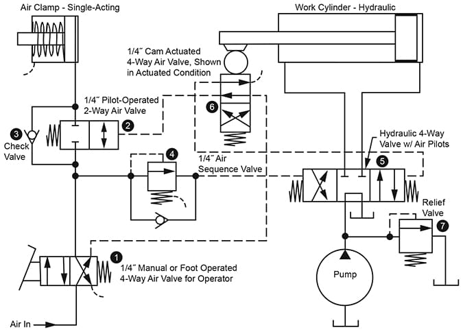
Figure 3. Interfacing Between Single-Acting Air Clamp and Hydraulic Work Cylinder
Interfacing Between Air and Hydraulics
Figure 3. An application sometimes overlooked is the use of an air clamp on a hydraulic operation. The hydraulic system will operate faster because no oil is supplied to the clamp. Air clamping is usually faster than hydraulic clamping, and the problem of supplying oil from one pump to two cylinders and dividing it between them is avoided.
Interfacing between the air clamp and the hydraulic cylinder can, of course, be done electrically, using limit or pressure switched and solenoid valves, but non-electrical operation using sequence valves offers certain advantages: components are less expensive; the clamp does not have to actuate limit switched, the placement of which may be critical; the work cylinder instantly stops if clamping force should be lost.
Interfacing to the hydraulics is best accomplished by using hydraulic 4-way valves with air pilots; most of the major manufacturers of hydraulic valves offer this kind of actuator. One of the design problems is to include a means for unloading the hydraulic pump between cycles. The circuit of Figure 3 accomplishes all the desirable objectives of clamp and work, and uses standard components. Accessories such as hydraulic filters, speed controls, etc., can be added as needed. Circuit action is as follows.
This application is set up to use a manual or foot-operated valve, 1, for operator control. When this value is shifted, air flows to the clamp cylinder. When clamping force is reached, the sequence valve opens and shifts the hydraulic valve to start the work cylinder. After completion of the work, the operator releases Valve 1. This diverts air pressure, through cam Valve 6, to the opposite pilot on hydraulic Valve 5 to retract the work cylinder. During retraction, clamping force is retained because Valve 2 blocks air flow out of the clamp. When the work cylinder reaches home, the cam Valve 5. Its spool centers and unloads the pump.
© 1990 by Womack Machine Supply Co. This company assumes no liability for errors in data nor in safe and/or satisfactory operation of equipment designed from this information.