Data Sheet 38: Designing Slow Feed Circuits – Part 2, Air Cylinders
Part 1 of this series, covering hydraulic cylinders, is in Design Data Sheet 28. The purpose of the present issue is to suggest circuit arrangements which will minimize the tendency of an air cylinder to “chatter” or move erratically when operated at a slow rate of travel.
Air cylinders are essentially power, not feed, devices. In general they should not be used to move metal cutting tools at a slow feed rate. An exception is for “crowding” a drill bit into the work; for this, the work resistance provides the stabilizing force. For slow feeding of milling machine tables, grinder tables, shapers or planers, hydraulics must be used.
Air cylinders perform best when operated at moderate to high travel speed. But where air power must be used at moderate to slow speeds, the ideas presented in this issue should prove helpful.
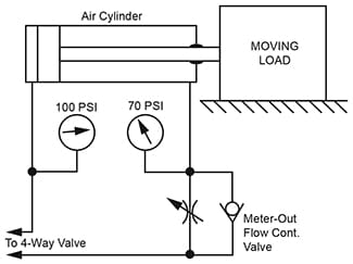
Figure 1. Speed Control Method. Experience shows that an air cylinder is less likely to chatter at low speed when “meter-out” rather than “meter-in” speed control is used. This puts a substantial pressure on both sides of the piston, thus increasing stability. The higher the back pressure, against the forward face of the piston, the greater the stability.
In order to have a high back pressure for stability, the cylinder bore should be large enough to give much more force than needed to just move the load. The greater the cylinder is overpowered with respect to the load, the higher the back pressure and the more stable the action will be.
For example, in Figure 1, if inlet pressure to the blind end is 100 PSI, and if pressure actually required to move the load is 30 PSI, this will give approximately 70 PSI back pressure. If the load should require 80 PSI just to move it, this would leave only 20 PSI back pressure and the cylinder would have a greater tendency to move erratically.
On existing systems, if the inlet pressure can be raised, this will give a higher back pressure under the same load and speed conditions. On new designs, the air cylinder should be oversized by 200 to 300% over the load resistance.

Figure 1. A high back pressure against the forward
surface of the piston increases stability at slow speed.
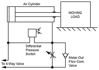
Figure 2. Pressure Differential Switching. While “meter-out” speed control as described above gives more stable operation, it presents a problem when a pressure sensitive device such as a pressure switch or sequence valve is to be installed at the blind end cylinder port for sequencing to a second operation.
A standard pressure switch, for example, teed into the cylinder blind port will not work well with meter-out speed control because it may be prematurely activated. The solution is to use a pressure switch of the “differential” type having two pressure sensing ports. These ports are teed into the two cylinder ports. The switch is then sensitive to the pressure difference across the cylinder.
While the cylinder is moving the load, the switch senses only the load pressure, and this is insufficient to trip its contacts. But when the cylinder stops against a positive stop, the differential pressure rises to full system pressure and closes the switch contacts. The pressure switch should be adjusted to trip very close to full system pressure so it will not momentarily trip when the load is first started.
A sequence valve can be connected to have an action similar to above. See Design Data Sheet 15.

Figure 2. For reliable action in a sequencing circuit,
a differential type pressure switch should be used if
the speed control valve is connected meter-out.
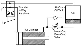
Figure 3. Air-Over-Oil System. This is a conventional, single-tank, air-over-oil system as described in Womack textbook “Industrial Fluid Power – Volume 2“.
The cylinder speed is metered in the forward direction as oil, pushed out ahead of the advancing piston, is forced through the flow control valve and into the air/oil tank. When the 4-way valve is reversed to retract the cylinder, air pressure on top of the oil in the tank forces the oil back into the rod end of the cylinder.
The 4-way valve is a standard air valve. The cylinder can be an air cylinder or low pressure hydraulic cylinder, but must have leak-tight piston seals.
The flow control valve controls cylinder speed only while it is extending. A double tank system must be used for speed control both directions. Refer to above source for more information.

Figure 3. Conventional single-tank, air-over-oil system.
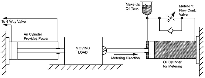
Figure 4. Metering Cylinder. An improved arrangement for oil metering of the speed of an air cylinder is shown. This method can be added without too much difficulty to an existing air system which does not operate smoothly at slow feed rates. This system has several important advantages over the straight air/oil system shown in Figure 3 above.
- The compressed air does not come into intimate contact with the metering oil. Therefore, there is no oil mist discharged into the atmosphere. In an air/oil system, some of the oil vaporizes into the air every cycle and is carried out the exhaust of the 4-way air valve.
- Since oil is not discharged into the atmosphere, it seldom has to be replenished. This reduces maintenance cost.
- If desired, an oil metering cylinder of very large volume can be used. The large flow through the flow control valve permits more accurate metering of speed.
- All components are catalog standard. No specially constructed air/oil tank is required.
- Only the small make-up tank has to be mounted at an elevation higher than the metering cylinder.
A second cylinder, rated for low pressure oil, is added for the sole purpose of metering an oil flow to control machine feed rate. Its placement depends on the physical layout of the machine. For simplicity of illustration it is shown attached to the load, although it could be attached to any moving part of the machine or even to the air cylinder. Its bore can be smaller or larger than the air cylinder bore, but the greater its volumetric capacity, the higher will be the oil flow during metering, and the more accurate will be the speed control.
During the metering stroke, oil is pushed from the blind end of the oil cylinder and metered through the flow control valve to the rod end. Surplus oil which cannot enter the rod end is stored in the make-up tank. On the return stroke this surplus oil again enters the system and flows freely to the cylinder blind end through the check valve.
Obviously, the make-up tank must have a greater volume than the volume of the cylinder piston rod. A compressed air line filter with plastic bowl and bowl guard makes an economical and satisfactory make-up tank.
The oil used in the metering cylinder should be very low viscosity and compatible with seals and the plastic in the make-up tank. ATF transmission fluid, Type A or Type F is a good fluid to use.
The oil cylinder is shown in Figure 4 to meter when the piston is pushed in. To make it meter when the piston is pulled out, move the make-up tank to the blind end port and turn the flow control valve around.
Note: Self-contained “hydraulic checking cylinders” can be purchased with self-contained flow control valve and reservoir. These units can be installed and adjusted so there is some fast free travel before the slow metering action starts.

Figure 4. An air powered system with oil metering for smooth travel at low speeds.
© 1990 by Womack Machine Supply Co. This company assumes no liability for errors in data nor in safe and/or satisfactory operation of equipment designed from this information.