Data Sheet 6: Hoisting and Cable Tensioning with Cylinders
Hoisting with Cylinders
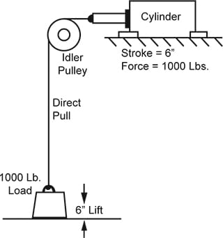
 | Figure 1 – Direct PullWhen used in a direct pull, with one cable supporting the load, the ratio between load lift height and cylinder stroke is 1:1. In this example, to raise a 1000 lb. weight a height of 6 inches, the cylinder must have a 6-inch stroke and must develop 1000 lbs. pull in retraction. Since the load is supported on one cable, the cable tension will be 1000 lbs. |
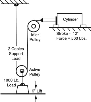
 | Figure 2 – One Cable WrapBy using suitable idler pulleys, two cables support the 1000 lb. load, with a tension of 500 lbs. in each cable. The cylinder-to-load ratio is now changed, and a 12-inch stroke is required to lift the weight a height of 6 inches, but the cylinder force is reduced to 500 lbs. |
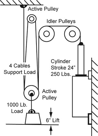
 | Figure 3 – Multiple Cable WrapThe use of additional idler pulleys and more wraps further changes the cylinder-to-load ratio. For example, with four cables supporting the load, the tension in each cable is reduced to 250 lbs. The cylinder stroke must be increased to 24 inches, but a pull of only 250 lbs. is required. Notice that cable tension, cylinder stroke, and cylinder pull are all changed in the same ratio as the change in the number of cables supporting the load. An interesting point to notice on the three hoisting examples is that whether a large bore, short stroke cylinder is used as in Fig. 1, or a smaller bore, longer stroke model as in Figs. 2 and 3, the lift capacity, lifting speed, hydraulic system PSI and GPM is identical in each case provided the cylinder is matched to the application. The same hydraulic pumping unit could be used with any of these arrangements. |
CYLINDER ECONOMICS…
The table shows that at the same HP input, a substantial savings can be realized by reducing the cylinder bore and increasing its stroke. This is the important advantage of a multiple wrap system. You can buy more HP per pound and per dollar with small bore, longer stroke cylinders.
| Cylinder Description | Weight, Lbs. | Price |
| 4″ bore x 6″ stroke | 55 | $176.00 |
| 2″ bore x 24″ stroke to do same job | 31 | $127.00 |
| 6″ bore x 6″ stroke | 155 | $385.00 |
| 3 1/4″ bore x 24″ stroke to do same job | 73 | $190.00 |
| 8″ bore x 6″ stroke | 310 | $675.00 |
| 4″ bore x 24″ sroke to do same job | 95 | $244.00 |
On multi-wrap systems, the savings on cylinder cost by using a smaller bore cylinder may be far greater than the extra cost of mechanical pulleys. Further advantages of a multi-wrap system are: lighter cylinder weight; and the cable, while longer, can be smaller in diameter, lighter in weight, more flexible, and can be less expensive.
One disadvantage of multiple wrap is the additional friction load of pulleys and other mechanisms, and the internal friction of the wire rope. The chart below, given by one authority, shows the extra pull to be added to make up for friction of active pulleys. For each idler pulley in the system, an additional 5 to 7% may also be needed.
2-part line (2 cables supporting the load) – add 18%
3-part line (3 cables supporting the load) – add 25%
4-part line (4 cables supporting the load) – add 33%

Figure 4 – Suspended Load on a Cable.
This is a simplified method of finding cylinder force for tensioning a cable, and was derived from trigonometry, although a knowledge of trig is not necessary in order to use the method. Ratio values in the left column of the chart are “cotangent” values taken from a standard table of natural trigonometric functions. Multipliers in the right column are “cosecant” values for the same angle. For intermediate ratio values or those beyond the chart, regular trig tables may be used.
Assume the weight of the cable is relatively small as compared with the suspended weight. Tension in each leg of the cable will be equal if the weight is hanging in the exact center of the cable. Otherwise, the tension will be different in each leg. Solve for each leg.
The first step, always, is to determine what percent of the load is supported by each leg of the cable. The load on each leg will be inversely proportional to distance A or A’ from weight to support. In Fig. 4, total span is 20 feet, so 9,000 lbs. (75% of the weight) will be supported by the short leg and 3,000 lbs. (25% of the weight) will be supported by the longer leg.
To solve for tension in a leg, after finding what per cent of the load it carries, take distance-A and divide it by the distance B (the sag) to find the ratio A ÷ B. Enter the left column of the chart and find this ratio. Use the multiplier from the right column to multiply times the portion of load carried by that leg. This gives the cylinder force necessary to support the load in this position.
If the exact value of your calculated ratio does not appear in the chart, interpolate between the next higher and next lower ratio; then interpolate in the same way to find the multiplier.
Solve for tension in short leg (Fig. 4): Ratio A ÷ B = 5 ÷ 2 = 2.50. Enter left column of chart and get multiplier, 2.69, on same line as ratio 2.50. Tension = 2.69 x 9,000 lbs. = 24,210 lbs.
Solve for tension in longer leg: Ratio A ÷ B = 15 ÷ 2 = 7.50. Enter left column of chart and find ratio 7.50. Use multiplier 7.57 shown on same line. Tension= 7.57 x 3,000 lbs. = 22,710 lbs.
In sizing a cylinder to tension the above cable, do not add tension in both legs. One cylinder will tension both legs of the cable. If pulling on the short leg, it must have 24,210 lbs. force; if pulling on the longer leg it must have 22,710 lbs. force.
A small difference in elevation between the two end supports will not seriously affect the accuracy of tension calculations. However, if the difference in elevation results in an angle between cable and horizontal of more than 10 to 15°, a more involved trigonometric calculation will have to be made.
Hydraulic Motor Torque…
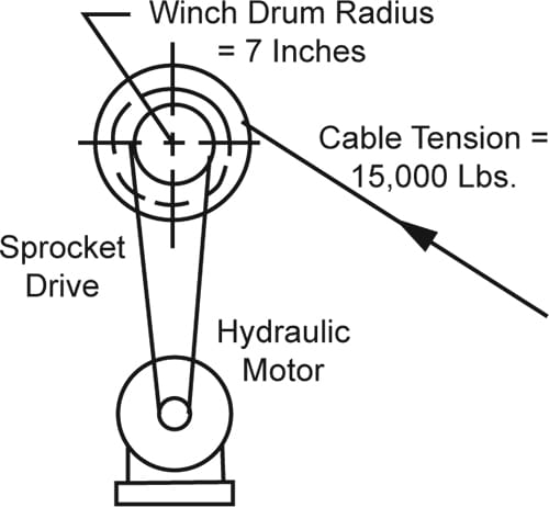
When pulling tension on a loaded cable with a winch drum driven with a hydraulic motor, use procedure described above for finding cable tension. Then solve for torque on winch drum by taking tension times drum effective radius. Then calculate theoretical motor torque by dividing drum torque by ratio between drum sheave or sprocket and hydraulic motor sheave or sprocket.

Example: Cable tension = 15,000 lbs; winch drum diameter 14 inches; winch drum drive sprocket diameter= 2 inches; motor sprocket diameter = 6 inches. Find theoretical torque required from the hydraulic motor.
Solution: Winch drum torque is 15,000 x 7 (radius of drum) – 105,000 inch-lbs. Motor torque is found by dividing winch torque by drive sprocket ratio. Torque= 105,000 / 2 = 52,500 inch-lbs. This is theoretical torque required on the motor shaft. Allow extra torque for mechanical losses in sprocket drive and in winch drum bearings.
| Ratio A + B | Multi- plier |
| 60.00 | 60.01 |
| 55.00 | 55.01 |
| 50.00 | 50.01 |
| 45.00 | 45.01 |
| 40.00 | 40.01 |
| 35.00 | 35.01 |
| 30.00 | 30.02 |
| 29.00 | 29.02 |
| 28.00 | 28.02 |
| 27.00 | 27.02 |
| 26.00 | 26.02 |
| 25.00 | 25.02 |
| 24.00 | 24.02 |
| 23.00 | 23.02 |
| 22.00 | 22.02 |
| 21.00 | 21.02 |
| 20.00 | 20.03 |
| 19.00 | 19.03 |
| 18.00 | 18.03 |
| 17.00 | 17.03 |
| 16.00 | 16.03 |
| 15.00 | 15.03 |
| 14.00 | 14.03 |
| 13.00 | 13.03 |
| 12.00 | 12.04 |
| 11.00 | 11.04 |
| 10.00 | 10.04 |
| 9.00 | 9.05 |
| 8.00 | 8.06 |
| 7.50 | 7.57 |
| 7.00 | 7.07 |
| 6.50 | 6.58 |
| 6.25 | 6.33 |
| 6.00 | 6.08 |
| 5.70 | 5.79 |
| 5.40 | 5.49 |
| 5.20 | 5.30 |
| 4.90 | 5.00 |
| 4.70 | 4.81 |
| 4.50 | 4.62 |
| 4.30 | 4.42 |
| 4.15 | 4.27 |
| 4.00 | 4.12 |
| 3.80 | 3.93 |
| 3.70 | 3.83 |
| 3.60 | 3.74 |
| 3.50 | 3.64 |
| 3.40 | 3.54 |
| 3.30 | 3.45 |
| 3.20 | 3.35 |
| 3.10 | 3.26 |
| 3.00 | 3.16 |
| 2.90 | 3.07 |
| 2.80 | 2.97 |
| 2.70 | 2.88 |
| 2.60 | 2.79 |
| 2.50 | 2.69 |
| 2.40 | 2.60 |
| 2.30 | 2.51 |
| 2.20 | 2.42 |
| 2.10 | 2.33 |
| 2.05 | 2.28 |
| 2.00 | 2.24 |
| 1.95 | 2.19 |
| 1.90 | 2.15 |
| 1.85 | 2.10 |
| 1.80 | 2.06 |
| 1.75 | 2.02 |
| 1.65 | 1.93 |
| 1.60 | 1.89 |
| 1.50 | 1.80 |
| 1.45 | 1.76 |
| 1.40 | 1.72 |
| 1.35 | 1.68 |
| 1.30 | 1.64 |
© 1988 by Womack Machine Supply Co. This company assumes no liability for errors in data nor in safe and/or satisfactory operation of equipment designed from this information.