Data Sheet 72: Horsepower Required for Compressing Air
This 3-part table shows the horsepower required to compress 1 SCFM (standard cubic foot per minute} of air from atmospheric pressure (0 PSIG} to the pressures shown in the table.
Values are shown for single-stage, two-stage, and three- stage piston-type air compressors operating at 85% efficiency, and working on intake air under standard conditions. Compression conditions intermediate between adiabatic and isothermal have been assumed (see explanation of these terms below). We believe this most nearly represents the condition which exists in the average plant air system. The table was prepared from information in Machinery’ Handbook. Please refer to your copy of the handbook for additional information on air compression and for the formula from which the table was calculated.
Horsepower has been calculated for compressors with 85% efficiency. If your compressor has an efficiency rating other than this, an allowance should be made in the table values.
EXPLANATION OF THE TABLE
The table is useful either in determining the HP for a new application or for checking the capacity of an existing system for addition of a large air cylinder reciprocating continuously for long periods. Figures are HP to compress 1 SCFM from 0 PSIG to the pressures shown. Calculate required SCFM from information in Design Data Sheet 58 and multiply times figure in the table.
Adiabatic Compression. This is defined as compression which takes place without allowing the escape of any of the heat of compression. Obviously this is a theoretical condition because cooling starts immediately after compression.
Isothermal Compression. This is compression which takes place while allowing dissipation of all heat of compression.
This is also a theoretical condition.
In calculating the table we have chosen a compression condition intermediate between adiabatic and isothermal.
HP Required to Compress Air
| Single-Stage Compressor, 85% Efficiency | Two-Stage Compressor, 85% Efficiency | Three-Stage Compressor, 85% Efficiency | |||
| PSIG | HP* | PSIG | HP* | PSIG | HP* |
| 5 | 0.021 | 50 | 0.116 | 100 | 0.159 |
| 10 | 0.033 | 60 | 0.128 | 150 | 0.190 |
| 15 | 0.056 | 70 | 0.138 | 200 | 0.212 |
| 20 | 0.067 | 80 | 0.148 | 250 | 0.230 |
| 25 | 0.079 | 90 | 0.155 | 300 | 0.240 |
| 30 | 0.089 | 100 | 0.164 | 350 | 0.258 |
| 35 | 0.099 | 110 | 0.171 | 400 | 0.269 |
| 40 | 0.108 | 120 | 0.178 | 450 | 0.279 |
| 45 | 0.116 | 130 | 0.185 | 500 | 0.289 |
| 50 | 0.123 | 140 | 0.190 | 550 | 0.297 |
| 55 | 0.130 | 150 | 0.196 | 600 | 0.305 |
| 60 | 0.136 | 160 | 0.201 | 650 | 0.311 |
| 65 | 0.143 | 170 | 0.206 | 700 | 0.317 |
| 70 | 0.148 | 180 | 0.211 | 750 | 0.323 |
| 75 | 0.155 | 190 | 0.216 | 800 | 0.329 |
| 80 | 0.160 | 200 | 0.220 | 850 | 0.335 |
| 85 | 0.165 | 210 | 0.224 | 900 | 0.340 |
| 90 | 0.170 | 220 | 0.228 | 950 | 0.345 |
| 95 | 0.175 | 230 | 0.232 | 1,000 | 0.290 |
| 100 | 0.179 | 240 | 0.236 | 1,050 | 0.354 |
| 110 | 0.191 | 250 | 0.239 | 1,100 | 0.358 |
| 120 | 0.196 | 260 | 0.243 | 1,150 | 0.362 |
| 130 | 0.204 | 270 | 0.246 | 1,200 | 0.366 |
| 140 | 0.211 | 280 | 0.250 | 1,250 | 0.370 |
| 150 | 0.218 | 290 | 0.253 | 1,300 | 0.374 |
| 160 | 0.225 | 300 | 0.255 | 1,350 | 0.378 |
| 170 | 0.232 | 350 | 0.269 | 1,400 | 0.380 |
| 180 | 0.239 | 400 | 0.282 | 1,450 | 0.383 |
| 190 | 0.244 | 450 | 0.289 | 1,500 | 0.386 |
| 200 | 0.250 | 500 | 0.303 | 1,550 | 0.390 |
*HP to compress 1 SCFM from 0 PSIG to the values shown.
MINIMIZING SHOCK IN HYDRAULIC SYSTEMS – PART 2
See Part 1 of this series in Design Data Sheet 23
The presence of shock in a hydraulic circuit indicates a change in energy level occurring in a short time interval. In decompression shock this is a very quick release of pressure and potential energy from a press cylinder. To reduce any kind of shock, some means must be provided to extend the time period over which the burst of energy is released (or absorbed).
On a hydraulic press, during the pressing operation, the cylinder frame and mechanical members in the press frame are stretched, and the oil behind the cylinder piston is compressed. When hydraulic pressure is suddenly released to reverse the cylinder, the frame members spring back to their original dimensions and the oil expands. If pressure is released in a matter of milliseconds, the mechanical shock can be quite severe. But if some means is provided to extend the release time over a period of 1 second, or perhaps several seconds, the mechanical shock will be greatly reduced.
Note: The use of any one of the circuits described in this sheet may not completely eliminate shock if the shock comes from more than one cause.

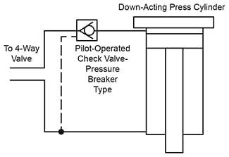
Figure 1. Using a PIlot-Operated Check Valve to
Decompress a Down-Acting Press Cylinder.
Figure 1. A simple and economical way to decompress the oil in a hydraulic cylinder is to use a pilot-operated check valve in the high pressure line to the cylinder.
A pilot-operated check valve has a main poppet which is biased by a light spring to a normally closed position. It will pass oil freely into the cylinder but will block return flow. In this respect its action is the same as a standard check valve. It also has a pilot piston which, when activated by pressure taken from the rod side of the cylinder, will push the poppet off its seat, allowing free flow in both directions.
The model selected should have a “pressure breaker”. This is a 2-stage construction in which a small poppet is built inside the large main poppet. When the 4-way valve is shifted to reverse the cylinder, pressure from the rod side of the cylinder opens the pilot-operated check valve. The small poppet is pushed open first, releasing a small volume of oil to reduce the oil pressure inside the cylinder to a relatively low value, 500 PSI for example. This gradually relaxes most of the stress on the press frame and allows the oil to expand. The rod end pressure is then able to open the large poppet in the pilot-operated check valve to permit the cylinder to retract. The decompression through the small poppet will minimize the hydraulic shock.
A 3-stage pilot-operated check valve model is offered by some manufacturers, and this can be used if available.
See Womack “Industrial Fluid Power-Volume 2” textbook for more information on pilot-operated check valves.

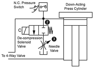
Figure 2. Bleed-Off Decompression of Electrically
Operated Hydraulic Press Circuits.
Figure 2. We recommend this decompression arrangement for electrically controlled presses. The idea here is to discharge a small flow to tank through a small solenoid valve after the pressing operation is complete and before reversing the 4-way valve. When pressure in the cylinder has dropped to a safe level, as sensed by the pressure switch, contacts on the pressure switch energize the main 4-way solenoid valve to retract the cylinder. The rate of decompression can be varied by setting the pressure switch adjustment to a safe level, 500 PSI for example, then adjusting the needle valve to control the length of time in which the decompression takes place.
The pressure switch should be adjustable. The “Com” and “N.C.” terminals would be used in this circuit. During the pressing operation, with high pressure in the cylinder, the pressure switch contacts would be held open and the solenoid 2-way valve would remain de-energized.
The solenoid valve is a 1/4˝ size, 2-way, normally closed model. Connections to the solenoid valve and the pressure switch must be integrated into the electrical circuit of the press in a way that the electrical signal for cylinder reversal is applied, not to the main 4-way valve, but to the solenoid of the decompression valve. When this valve opens, oil from the cylinder discharges through the needle valve to tank. When cylinder pressure has dropped to a safe level, the pressure switch contacts close and transfer the reversing signal to the main 4-way valve to reverse the cylinder. The circuit should also be arranged to unload the pump during the decompression period. We suggest the unloading circuit shown in Figure 4 on Design Data Sheet 23.

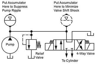
Figure 3. Accumulators Are Effective in Some Cases
of Pump Ripple or Valve Shifting Shock.
Figure 3. An accumulator may diminish shock if placed as close as possible to the component producing the shock. It is more effective for diminishing a regularly spaced pressure ripple as from a piston pump than it is for dampening a random impulse as from a shifting valve.
For rule-of-thumb sizing, select a model with no more than 1/10th the capacity of the GPM flow rate in the system. Initially pre-charge it to one-half the maximum hydraulic pressure. Experiment by reducing the pre-charge level until the point of best shock suppression is found.
A diaphragm or bladder-type accumulator has a faster response than a piston-type, and may be more effective.
© 1990 by Womack Machine Supply Co. This company assumes no liability for errors in data nor in safe and/or satisfactory operation of equipment designed from this information.