Data Sheet 71: Vehicle Drive with Hydraulic Motors – Part 2
Please refer to Part 1 of this series which appeared in Design Data Sheet 41. We are primarily concerned with hydraulic motor drive of off-the-road vehicles, but the data in these sheets are also applicable for direct engine drive. This is a condensation of some of the material in the Womack book “Industrial Fluid Power – Volume 3” and the reader is referred to that source for more detailed information.
Drawbar Pull
The accepted way of calculating a vehicle drive is to start with linear units the desired travel speed in MPH or feet per second, and drawbar pull which is the total horizontal force required to overcome all resistances to movement and acceleration. When these linear values have been specified or calculated they can be converted to rotary values, and motor or axle torque and wheel RPM can be easily calculated. Horsepower requirements can also be determined.
Drawbar Pull to Overcome Road Resistance
Clark Equipment Co. publishes the following figures for estimated drawbar pull for a rubber tired vehicle traveling on the level, to keep it in steady motion after it has been set in motion. Figures in the table are for each 1,000 lbs. of vehicle weight, including personnel.
Because of wide variations in the same type of road surface, the table should be used with discretion. Drawbar pull requirements may vary with wheel diameter on the same road surface. Vehicles with relatively large wheels may use the minimum values; those with unusually small wheels should use the higher values in the table.
| Concrete – 10 to 20 lbs. | Snow – 22 to 37 lbs. |
| Asphalt – 12 to 22 lbs. | Dirt – 25 to 37 lbs. |
| Macadam – 15 to 37 lbs. | Mud – 37 to 150 lbs. |
| Cobbles – 55 to 85 lbs. | Sand – 60 to 300 lbs. |
Drawbar Pull to Overcome Grade Resistance
If the vehicle is required to climb a grade, under load, the additional drawbar pull, according to the grade, must be calculated and added to that already calculated for the road surface.
In vehicular work, grade is usually expressed in per cent rather than in degrees. Grade per cent is the vertical rise as a percentage of horizontal distance. For example, a 2% grade is a rise of 2 feet in a distance of 100 feet. Percent grade is written as a decimal. A 2% grade would be written 0.02.
F1 = W × GR
in which: F1 is the added draw bar pull, in pounds.
GR is the grade resistance expressed in
percent and written as a decimal.
This formula gives approximate solution for most grades, which are rarely steeper than 25%. For steeper grades use the trigonometric solution: F = W × sine of grade angle.

Drawbar pull is the horizontal propelling force required to overcome all resistances to vehicle movement.
Drawbar Pull for Rapid Acceleration
Additional drawbar pull, over that required for road resistance and grade resistance is required for fast acceleration from a standstill or from a lower to a higher speed. On most off-the-road vehicles this force is small, usually negligible, but can be checked with this formula:
F2 = w × [V2 – V1] ÷ [32.2 × T]
in which: F2 is the added draw bar pull, in pounds.
V1 is the starting velocity, in feet per second.
V2 is the final velocity, in feet per second.
W is gross vehicle weight, in pounds.
T is the time, in seconds, to bring the vehicle
from velocity V1 to velocity V2
32.2 is g = acceleration of gravity.
Drawbar Pull for Wind Resistance
On vehicles moving at less than 20 MPH wind resistance should not be a major factor. Calculate the extra drawbar pull to overcome wind resistance on faster vehicles with this formula. Remember that results are approximate because the frontal shape may make a big difference in wind resistance. A table of factors for various frontal profiles is given in the appendix to Chapter 3 in the book “Industrial Fluid Power – Volume 3”.
F3 = 0.0025 × A × S2
in which: F3 is additional draw bar pull, in pounds.
A is frontal area of vehicle, in square feet.
S is vehicle speed, in miles per hour (MPH).
Other Factors to Be Considered
When using hydraulic motors for wheel drive, starting torque must be considered. The starting torque for the average hydraulic motor is about 3/4 its rated running torque. If starting torque is important, design with extra drawbar pull as needed.
Designing a vehicle with sufficient drawbar pull to meet all resistances at the same time may not be necessary and may result in over-powering. For example, the specification on force for acceleration may be required on an empty vehicle but may be waived when the vehicle is fully loaded. Or, the road surface when climbing a grade may be better than calculated for level operation. In order to keep the required HP to a reasonable level it may be necessary to make certain compromises.
Be sure also to allow additional drawbar pull to overcome frictional resistances in the vehicle drive train, wheel bearings, etc. Transmission losses, of course, will vary quite widely, and the designer should use his carefully considered best judgement on the amount of power loss to be expected.
Example Calculation of Drawbar Pull
Find total drawbar pull for this application: Vehicle weight 20,000 lbs.; 3% grade; relatively small vehicle wheels; acceleration from standstill to 10 MPH in 10 seconds.
Solution: Since the wheels are relatively small, use the maximum value of 37 lbs. for dirt road. Road resistance is 20 × 37 = 740 lbs. Grade resistance is 20,000 × 0.03 = 600 lbs. Acceleration force is [10,560 × 15] ÷ [32.2 × 10] = 492 lbs. Total drawbar pull = 740 + 600 + 492 = 1,832 lbs. See table for conversion MPH to feet per second.

Figure 2. Torque equals drawbar pull times wheel radius.
Conversion of Drawbar Pull to Wheel Torque
Figure 2. Wheel torque must be sufficient to produce a thrust against the road equal to the drawbar pull needed. After determining the total drawbar pull to meet all operating conditions, convert it to torque by multiplying times wheel radius, using the proper units.
T = F × R
in which: T is axle torque, in inch-lbs.
F is total drawbar pull, in pounds.
R is wheel radius, in inches.
Selecting a Hydraulic Motor for Vehicle Drive
Wheel motors provide probably the most efficient means of driving the wheels. High speed standard motors usually must be coupled through a speed reducer, a gear box or chain drive. For good efficiency and performance, the motor should be allowed to run at its maximum rated speed at the vehicle specified maximum speed. When run at less than its maximum speed its performance tends to deteriorate and its speed regulation becomes increasingly poor.
Traction with the Road
All the engine HP in the world will do no good unless the wheels can get a grip on the road. Traction is an equal and opposing force to drawbar pull. Vehicle traction must be as great or greater than drawbar pull. In Design Data Sheet 41 and in the book “Industrial Fluid Power – Volume 3” there are rules for load distribution and for the number of wheels which must be powered to get sufficient traction.

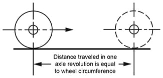
Figure 3.
Calculation of Wheel RPM
Figure 3. Each time the wheel makes one revolution, the axle travels a linear distance equal to wheel circumference. To solve for RPM, the linear speed of the vehicle should be stated in “inches per minute”. Use this table for easy conversion from MPH to inches per minute. Use the following formula for calculation of wheel RPM.
RPM = L ÷ C
in which: L is distance, in inches, traveled in one minute.
C is wheel circumference, in inches.
| MPH | Ft/Sec | Ins/Min |
| 5 | 7.3 | 5,280 |
| 10 | 15 | 10,560 |
| 15 | 22 | 15,840 |
| 20 | 29 | 21,120 |
| 25 | 37 | 26,400 |
| 30 | 44 | 31,680 |
| 35 | 51 | 36,960 |
| 40 | 59 | 42,240 |
| 45 | 66 | 47,520 |
| 50 | 73 | 52,800 |
| 55 | 81 | 58,080 |
| 60 | 88 | 63,360 |
Computing HP for Vehicle Drive
Output HP of the vehicle can be computed in mechanical terms using velocity and draw bar pull, with the standard HP formula:
HP = F × V ÷ 33,000
in which: F is the drawbar pull provided, in pounds.
V is the velocity, in feet per minute
33,000 ft-lbs/minute equals 1 HP
Drive HP for the system may be considerably higher depending on the particulars of each system. A hydraulic motor for wheel drive is usually figured at 85% efficiency. Efficiency of the mechanical drive train including gear boxes, chain drives, etc. will vary widely. Efficiency figures can sometimes be obtained from the manufacturer of the item. Efficiency in the remainder of the hydraulic system must also be taken into account. On a simple, straightforward system the efficiency through the hydraulic system including pump, motor, valves, lines, etc., may be approximately 50%.
Pulling a Trailer
Calculate drawbar pull for each unit separately for road resistance, grade resistance, acceleration, etc., then combine for total pull required. Check for road traction as per Design Data Sheet 41 using only the weight over the powered axles of the tractor. Apply hydraulic motor drives to as many axles as necessary to get the traction required.
© 1990 by Womack Machine Supply Co. This company assumes no liability for errors in data nor in safe and/or satisfactory operation of equipment designed from this information.